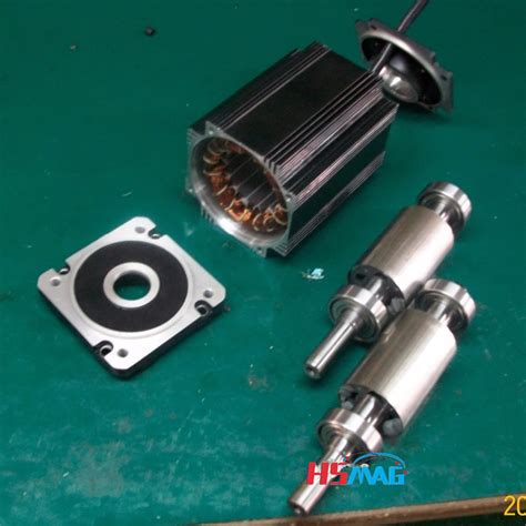
Permanent magnet rotor e1655961736623.jpeg.
To solve the problem of tension stress caused by centrifugal force and caused by high-speed operation of permanent magnet (PM) rotor, a FeCo-based PM rotor structure model is proposed. Based on …
Since the pole arc coefficient of the rotor permanent magnet is 0.5, according to Ref. 28, the magnetomotive force generated by the permanent magnet is equal to that generated by the adjacent FMP.External rotors of “outrunner” type. Rotors with additional bandage (Polyglas, Kevlar, carbon) Rotors with protecting sleeve. Contact us. Jan Kratochvil ml. +420 607 570 823 [email protected]. We will be happy to cooperate on development and manufacturing of rotors with permanent magnets, please contact our specialist. Leave …Permanent Magnet (PM) Brushless Direct Current (BLDC) actuators/motors have many advantages over conventional machines, including high efficiency, easy controllability over a wide range of operating speeds, etc. There are many prototypes for such motors; some of them have a very complicated construction, and this ensures their …
The main objective of this paper is to design and analyze the performance of in-wheel outer rotor permanent magnet synchronous motor (PMSM) used in electric vehicles based on a previously designed ...Non−Magnetic Rotor Core Rotor Magnets Rotor Pole Pieces Figure 2: Axial View of a Flux Concentrating Motor The geometry of one type of internal magnet motor is shown …In this study, a three‐phase outer rotor PMaSynRM with a power of 1 kW and a speed of 750 rpm was designed. The stator and rotor geometric structures of the designed motor were determined. The combination of slots/poles …
Purpose This paper comprehensively analyses the radial electromagnetic (EM) force by unit area and vibration characteristics in a permanent magnet synchronous motor (PMSM). This provides the possibility to verify the action law, causes, and influencing factors of vibration deformation and provides new ideas for vibration management. …
Similar to type Ⅰ, this configuration also forms a series magnetic circuit between the inner stator, outer stator and rotor. The rotor structure of type Ⅲ is similar to that of type Ⅱ, but the magnetisation direction of the inner and outer PMs located on the same axis are opposite. In this rotor structure, the rotor yoke contains ...where B m is the maximum air gap flux density (0.4–0.9 T), B r,m is the remanence flux density of the magnets (1.2 T) at the operating temperatures of the outer rotor PMSG, is the relative permeability of the …An ironless rotor structure wastes permanent magnet material, since the magnetic circuit closes through air in the rotor side. Therefore, a thin steel rim, to which the magnets are attached, is employed (Fig. 9.1) The rim can be either a laminated structure, in which case the eddy current losses of the rotor remainHow can a flux-absorbing structure improve the performance of a surface-mounted permanent magnet motor? This paper presents a comprehensive study of the electromagnetic and thermal characteristics of such a motor, using finite element analysis and experimental validation. The results show that the proposed structure can enhance …In this paper, a novel dual mechanical port dual rotor counter-rotating permanent magnet flux switching generator (DMPDRCR-PMFSG) for wind turbine applications is proposed. Power distribution between the inner and outer rotors of the proposed DMPDRCR-PMFSG that contributes to the cumulative output power is …
This control method can control the AC permanent magnet servo motor as a DC permanent magnet motor in a sense. According to Equations (1)–(3), the second-order dynamic equation of the position ring of the PMSM is expressed as follows: (4) { θ ˙ = ω ω ˙ = b i q + d (4) where b = 1.5 p n ψ f / J is a disturbance composed of unknown friction …
Jul 30, 2022 · In this paper, an improved rotor position observer with sliding mode control strategy of permanent magnet synchronous motor was studied. A MPF was designed instead of LPF to reduce the chattering in the traditional SMO back EMF and eliminate the system phase delay.
Rotor The rotor is made of permanent magnet and can vary from two to eight pole pairs with alternate North (N) and South (S) poles. Based on the required magnetic field density in the rotor, the proper magnetic material is chosen to make the rotor. Ferrite magnets are traditionally used to make permanent magnets. As the technology advances, rare Feb 9, 2018 · Electric machines with permanent magnet rotors are becoming increasingly popular due to the high power density that they offer relative to other configurations. Where the speed of rotation is high, the magnets are typically mounted on the surface of the rotor and retained by an outer sleeve. In the literature, a variety of analytical models have been proposed to aid the mechanical design ... This paper presents a design method of the basic model of high-speed surface-mounted permanent magnet synchronous motor (SPMSM) comprehensively considering the mechanical and electromagnetic properties based on the subdomain method. In the rotor design stage, the mechanical stresses of the permanent magnet …where B m is the maximum air gap flux density (0.4–0.9 T), B r,m is the remanence flux density of the magnets (1.2 T) at the operating temperatures of the outer rotor PMSG, is the relative permeability of the …2.2 External rotor permanent magnet motor rotor air gap magnetic field When the motor is running at no load, the air gap magnetic field is provided by the permanent magnet alone. The generated magnetic field rotates together with the rotor and the rotational speed is synchronous speed.
Rotor The rotor is made of permanent magnet and can vary from two to eight pole pairs with alternate North (N) and South (S) poles. Based on the required magnetic field density in the rotor, the proper magnetic material is chosen to make the rotor. Ferrite magnets are traditionally used to make permanent magnets. As the technology advances, rare Apr 8, 2022 · This paper proposes two structures of dual-stator permanent-magnet vernier machines (VMs) for high-torque low-speed applications. The proposed structures consist of dual-sided rotor which is sandwiched by inner and outer stators. These topologies include 22 and 46 consequent-pole magnets in the rotor and 24 and 48 stator slots for Design A and Design B, respectively. Design A is an improved ... The prototype machine is an axial-flux permanent-magnet machine with a two-rotor–one-stator configuration. The nominal power of the machine is 300 W and the nominal rotational speed is 500 rpm. The magnets are neodymium iron boron magnets. Twelve magnets are mounted on the rotor surface and 12 magnets buried on the rotor (Fig. 12a). This paper compares two flux-switching machines, namely, one stator permanent magnet flux-switching machine and one rotor permanent magnet flux …For high-speed permanent magnet synchronous motors (HSPMSM), the rotor eddy current loss is generated by the time and the space harmonics, which results in the rotor temperature rise. This paper deals with the design and analysis of a 100kW, 20000r/min HSPMSM with novel composite rotor. The novel composite rotor includes a shaft, …A flux-reversal permanent-magnet motor with the magnetic-differential application is presented in this paper. The motor adopts radial-field double-rotor structure. By artfully integrating a set of windings into the motor, the motor is able to realize differential without the bulky differential gear, making the propulsion system in electric vehicles more …More specifically, the rotor itself contains permanent magnets, which are either surface-mounted to the rotor lamination stack or embedded within the rotor …
Purpose This paper comprehensively analyses the radial electromagnetic (EM) force by unit area and vibration characteristics in a permanent magnet synchronous motor (PMSM). This provides the possibility to verify the action law, causes, and influencing factors of vibration deformation and provides new ideas for vibration management. …
Non−Magnetic Rotor Core Rotor Magnets Rotor Pole Pieces Figure 2: Axial View of a Flux Concentrating Motor The geometry of one type of internal magnet motor is shown (crudely) in Figure 2. The permanent magnets are oriented so that their magnetizationis azimuthal. They are located between wedges of magnetic material (the pole pieces) in …In this study, a three‐phase outer rotor PMaSynRM with a power of 1 kW and a speed of 750 rpm was designed. The stator and rotor geometric structures of the designed motor were determined. The combination of slots/poles …In this study, a three‐phase outer rotor PMaSynRM with a power of 1 kW and a speed of 750 rpm was designed. The stator and rotor geometric structures of the designed motor were determined. The combination of slots/poles …Sep 17, 2020 · Differently from the surface-mounted permanent magnet (PM) synchronous motors, there is an asymmetry of the reluctance between the d-axis and the q-axis, in which saliency can be used to produce reluctance torque in addition to the magnet torque, thus improving the efficiency. In addition, the IPMSMs provide more rotor robustness as magnets are ... Non−Magnetic Rotor Core Rotor Magnets Rotor Pole Pieces Figure 2: Axial View of a Flux Concentrating Motor The geometry of one type of internal magnet motor is shown (crudely) in Figure 2. The permanent magnets are oriented so that their magnetizationis azimuthal. They are located between wedges of magnetic material (the pole pieces) in …Nov 27, 2021 · In this study, an analytical model is established to efficiently compute the magnetic field and unbalanced magnetic pull (UMP) in axial-flux permanent-magnet motors (AFPMMs). The effects of stator slotting, end effect, and rotor eccentricity on the magnetic field and forces were investigated. Static and dynamic eccentricities are analyzed and considered in the model. An effective function of ... Rotor configurations strongly affect the torque and efficiency performance of permanent magnet electric motors. In this paper, different rotor configurations of the permanent magnet BLDC motor ...
In order to address these issues, a 2-DOF surface permanent magnet spherical motor with a new mechanical design for the movement of the rotor with a large tilt angle of ±45° was designed, simulated, produced and tested in this paper. The motor consisted of a 4-pole permanent magnet rotor and a 3-block stator with 18 coils.
This paper presents an analysis of torque pulsation with respect to the rotor rib shape in an interior permanent magnet motors (IPMs) and the type of magnet materials. The effects of three parameters, the angle and length of the flux barrier and the residual flux density of the PM, are studied using the response surface methodology. …
The permanent magnet motor tends to have larger step angles, 7.5° or 15°, than the variable reluctance motor. The hybrid motor typically has 200 rotor teeth and rotates at 1.8° step angles. They have high static and dynamic torque and can run at very high step rates. As a consequence they are very widely used. When the rotor magnets are placed inside the rotor iron in PMSM, the machine is called interior permanent magnet (IPM) . In this case, the magnetic reluctance is not uniform as it was for SM-PMSM. So, the self-inductance value of the stator will depend on the rotor position and, consequently, there will be nonzero reluctance torque in addition to the …Apr 8, 2022 · This paper proposes two structures of dual-stator permanent-magnet vernier machines (VMs) for high-torque low-speed applications. The proposed structures consist of dual-sided rotor which is sandwiched by inner and outer stators. These topologies include 22 and 46 consequent-pole magnets in the rotor and 24 and 48 stator slots for Design A and Design B, respectively. Design A is an improved ... The demagnetization of rotor permanent magnet is described in terms of rotor offset caused by demagnetization, demagnetization angle, decrease of air-gap MMF at the demagnetization …Since the teeth of the stator and the magnetic bridge of the rotor are prone to magnetic saturation, the grids in these places are encrypted, as shown in Figure 2. The specific mesh settings are as follows: stator teeth 0.2 mm, stator yoke 2 mm, rotor edge 0.2 mm, rotor yoke 2 mm, and permanent magnet 2 mm.In their work, a range of electric machine options are considered and it is concluded that a synchronous machine with a permanent magnet (PM) rotor will be the most efficient and power dense. In addition to applications in turbocharging, Gerada [ 3 ] highlight an increasing demand for high-speed electrical machines in flywheel energy …The SPMSM has the permanent magnets fixed on the surface of the rotor leading to a symmetrical radial air-gap reluctance path between the rotor and the stator core. The IPMSM has the permanent magnets inserted inside the rotor core leading to a non-symmetrical radial air-gap reluctance path between the rotor and the stator core. 1 Introduction. Flux-switching permanent-magnet (FSPM) motors have advantages such as high-power and -torque density, high efficiency and simple and robust mechanical structure in the rotor [1-4].These motors have bipolar flux linkage and sinusoidal back-electromotive force (EMF) [].In FSPM motors, because of the placement of …A high-speed (HS) permanent magnet (PM) synchronous motor (HSPMSM) with a carbon fiber-reinforced plastic (CFRP) protective sleeve in the surface-mounted rotor was explored in this study.A computationally efficient design of interior permanent magnet (IPM) motor rotor features is investigated utilizing analytical methods. Over the broad operating range of IPM machines, interactions of MMF sources, permeances, and currents result in torque harmonics. The placement of traditional rotor features along with sculpt features are …
The fundamental operation of a permanent magnet motor is like most electric motors; the outer stator holds windings of coils fed by a power source, and the rotor freely rotates based on the forces imparted by the stator coils. Many of the same basic principles for induction motors hold true for permanent magnet motors, and more information can ... A post-assembly magnetizing fixture has been designed and successfully used to magnetize the rotor of a 100 kW high speed permanent magnet synchronous motor. The rotor is a solid cylinder with outer diameter of 80 mm and total length of 515 mm. The permanent magnet material is samarium-cobalt (Sm 2 Co 17) withInstagram:https://instagram. otcmkts ozscharoldpercent27s on sangamonsks ayrany qmblexercise science bachelorpercent27s This study proposes design procedures for the permanent-magnet-biased magnetic bearings (PEMBs) in rotor systems. Many aspects of designing magnetic … fc2 ppv 3324320redding california 10 day weather forecast Feb 21, 2023 · An interior permanent magnet synchronous motor (IPMSM) with ‘VV—’ shape rotor topology structure is proposed. The established two-dimensional (2D) parameterized finite element analysis (FEA) models are used to analyze and compare the output average torque, torque density, air-gap flux density and back electromotive force (EMF) of the IPMSM with ‘V’ shape, ‘V—’ shape, ‘VV ... zlecenia A permanent magnet rotor assembly is a crucial component in various applications, including BLDC motors, generators, and magnetic couplings. It consists of a rotor with permanent magnets, such as neodymium magnets, mounted on it to ensure an efficient and reliable magnetic field generation. The interaction between the magnetic field …Jun 23, 2022 · The rotor overtemperature caused by losses is one of the important issues for the high-speed electrical machine. This paper focuses on the rotor loss analysis and CFD-thermal coupling evaluation for 105 kW, 36,000 r/min HSPMSM. Three types of sleeve materials as carbon-fiber, Titanium alloy, and stainless steel are introduced in this paper, researching the effects of sleeve conductivity ... where B m is the maximum air gap flux density (0.4–0.9 T), B r,m is the remanence flux density of the magnets (1.2 T) at the operating temperatures of the outer rotor PMSG, is the relative permeability of the …